


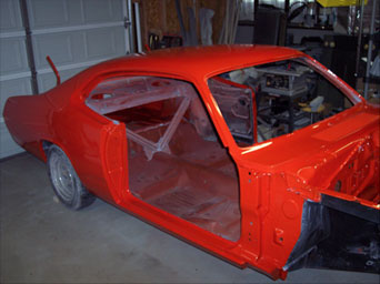
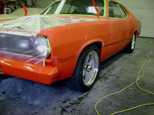
With 99.9% of the paint work completed on Dec. 1, 2007, the time had finally arrived to begin putting this thing back together.
In mid-December I began by installing fuel and brake plumbing.
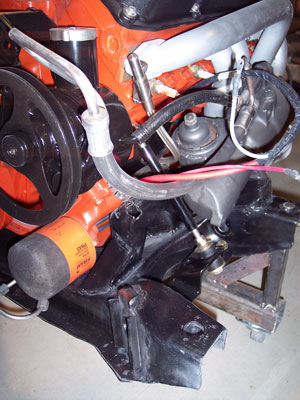
Plumbing items came from Finelines, Inc. First to go in was the 3/8 fuel line that runs from front to rear. Right away, I ran into a problem when I realized that the one-piece fuel line could not be threaded through the front crossmember because the right side frame connector prevented me from raising it up into position on the underside of the body
In mid-December I began by installing fuel and brake plumbing.
Plumbing items came from Finelines, Inc. First to go in was the 3/8 fuel line that runs from front to rear. Right away, I ran into a problem when I realized that the one-piece fuel line could not be threaded through the front crossmember because the right side frame connector prevented me from raising it up into position on the underside of the body
It wasnt a problem with the frame connectors or their installation, mind you. It was simply a combination of the length of the fuel line with its various bends, and the law of physics. The line had to cross from along the rocker, above the frame connector before continuing forward and through a small hole in the crossmember. It was going to have to go in in two pieces.
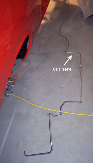
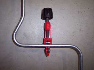
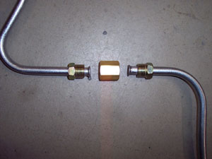
So, out comes the tubing cutter and flair tool with a union to re-join the two pieces.
The front to rear brake line was next along with rear hose, differential brake lines, and wheel cylinders.
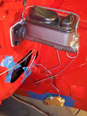
The front brake lines are a special kit produced by Finelines for stock drum to disc conversion. That kit called for an aftermarket proportioning valve. I ordered everything from them in early 2007. Sometime later in the year a stock style proportioning valve become available so all of those lines should now be identical to the originals.
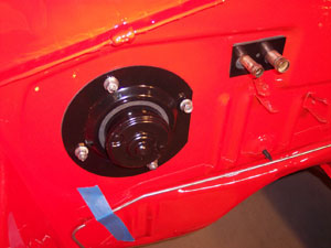
I installed the master cylinder (a late 70s disc brake unit for trucks) and mocked up the lines.
UPDATE: The truck MC has a 1.125" bore which requires a fair amount of leg to bring the car to a stop. Not ideal for emergency braking. I later switched to an aluminum 1.03" MC from Dr. Diff which worked much better. He includes a billet 2-bolt adaptor with the unit - all at a very reasonable price.
The front brake lines are a special kit produced by Finelines for stock drum to disc conversion. That kit called for an aftermarket proportioning valve. I ordered everything from them in early 2007. Sometime later in the year a stock style proportioning valve become available so all of those lines should now be identical to the originals.
I installed the master cylinder (a late 70s disc brake unit for trucks) and mocked up the lines.
UPDATE: The truck MC has a 1.125" bore which requires a fair amount of leg to bring the car to a stop. Not ideal for emergency braking. I later switched to an aluminum 1.03" MC from Dr. Diff which worked much better. He includes a billet 2-bolt adaptor with the unit - all at a very reasonable price.
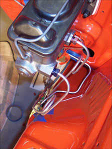
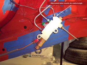
It took some emails to Finelines to learn that the aftermarket valve was intended to be mounted at an odd angle relative to the frame rail. A long, self tapping bolt (not included) threads into a hole in the rail. Now that was all sorted out and the valve to MC lines were tweaked slightly, everything looks and works fine.
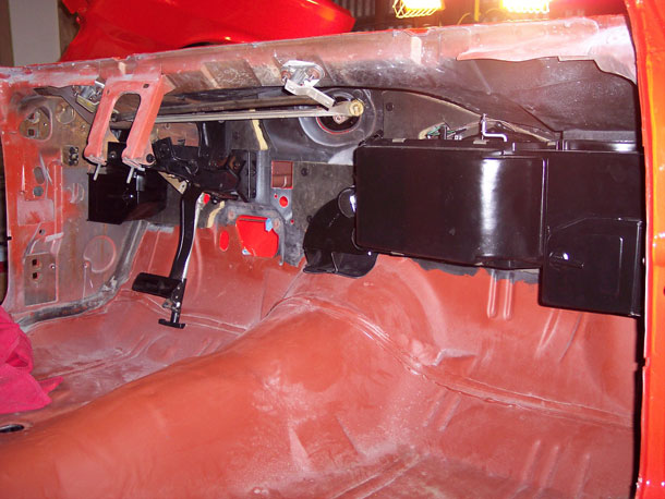
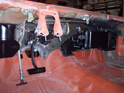
The rebuilt wiper pivots and original motor were reinstalled. The original dash insulation, which was in good shape, went in with new barbed push pins. The heater box, drivers air vent, and pedal assemblies also went in - all very quickly.
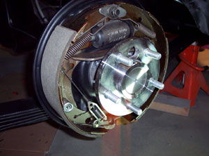
The rear brakes were buttoned up along with their individual e-brake cables. Those cables, originals on the car, were media blasted prior.
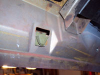
A new vinyl covered e-brake cable was routed from the front to the equalizer at the rear. I had drilled new holes for it when I installed the frame connectors as one of the connectors covered the factory hole in the trans crossmember
The installation of the B&M cable shifter was also worked out. Thats covered under Interior.
The new fuel tank was installed (sorry, no pics) along with an insulation pad I made. I should note that I pre-installed a new 3/8 sender in the tank. The pickup on the aftermarket sending unit hit the bottom of the tank, preventing it from seating properly. I ended up bending the pickup tube enough so that it would seat properly in the tank. It was tough stuff and did not bend easily. Of course, I also made sure the sender range was between about 9 and 73 ohms while moving the float up and down. Fixing the sender was a time consuming hassle so watch out for this if you replace yours.
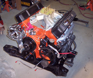
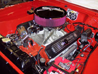
In early January 2008 the time had finally arrived to install the engine and tranny - hopefully once and for all!
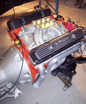
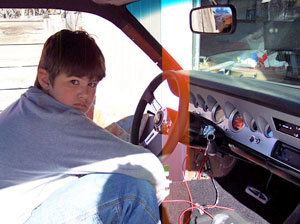
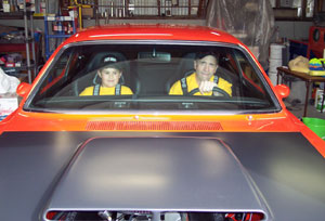
Seen here in near full-dress, my 10 year old son and I are just moments away from raising the front of the car rolling it underneath.
We took the time to install a fresh set of platinum spark plugs so we wouldnt have to mess with it once in the car and space became nill.
Seen here in near full-dress, my 10 year old son and I are just moments away from raising the front of the car rolling it underneath.
We took the time to install a fresh set of platinum spark plugs so we wouldnt have to mess with it once in the car and space became nill.
Once that was in we started reassembly of the front suspension and steering.
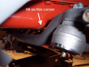
I made the mistake of not pre-assembling the idler and centerlink prior to installing the engine in the car. I found that the centerlink hit the correct stock oil pan for this conversion (stamped: 187) when the wheels were turned to the right.
After spending days researching what I might have done wrong and turning up nothing, I simply ground some paint off, warmed the pan, and hammered the offending corner flat. It didnt take much, and we were back in business.
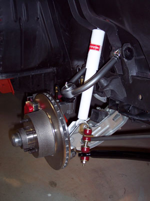
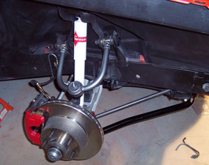
Reassembly of the front suspension, brakes, and steering proceeded including the addition of front and rear Addco sway bars.
The front sway bar mounts to the front lip of the K-Member with brakets that bolt to existing holes.
The end links are attached to a bracket that bolts to the lower shock mount using the shock bolt.
I wasnt super impressed with the arrangement of all this and the fit was less than ideal. For example, the end link brackets had to be ground in order for them to fit flush against the lower control arm. The bar is also a tad too wide so the end links are canted out at an angle on both sides rather than vertical, and at least one of the mounts on the K-Frame is too close to the front strut bushing. All of these brackets should really be welded rather than bolted - which I may still do - but not until I see how it performs.
The rear sway bar was marginally better but it wont win any awards for elegance with all the brackets and u-bolts, and stuff.
A couple of notes. I had planned and hoped to mount the brake calipers toward the front and not the rear. Unfortunately, they hit the very end of the sway bar when the wheels were turned. This also forced a less than ideal routing for the brake hoses. They routed very well without touching anything with the calipers on the front. They work okay with the calipers on the rear but Im going to have to keep an eye on them.
One final note: The upper ball joint boots supplied with the tubular control arms were worthless. They just flopped around loose. A pair of polyurethane ones from Energy Suspension work perfectly.
One final note: The upper ball joint boots supplied with the tubular control arms were worthless. They just flopped around loose. A pair of polyurethane ones from Energy Suspension work perfectly.
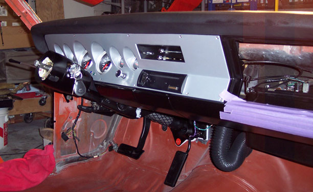
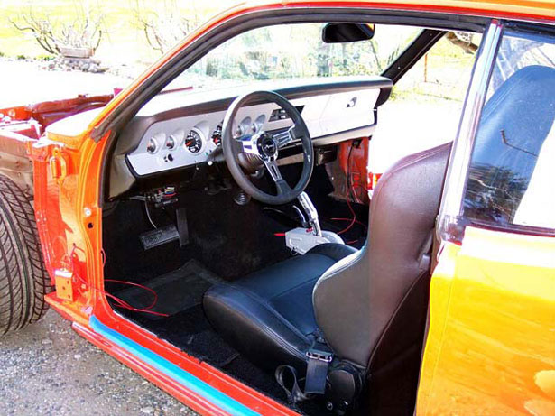
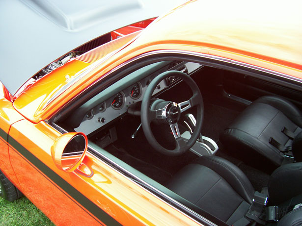
With the dash pre-assembled, it went back in as a unit very easily - just like the factory would have done. I left the glove box door off in order to more easily connect the heater control cables.
The steering column went in with identical ease. With the bolts snugged down and the roll pin back in the steering coupler it was just a matter of econnecting the e-brake handle and plugging the bulkhead connector back into the firewall.
The steering column went in with identical ease. With the bolts snugged down and the roll pin back in the steering coupler it was just a matter of econnecting the e-brake handle and plugging the bulkhead connector back into the firewall.
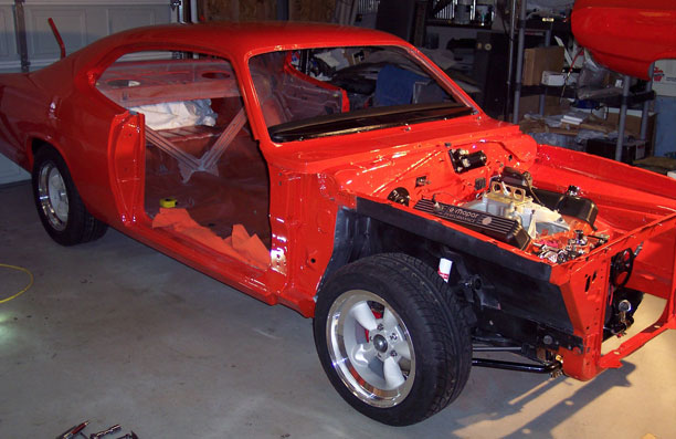
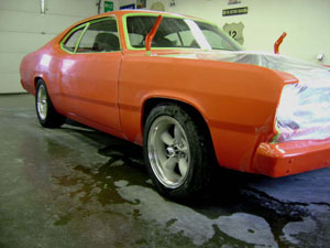
...And, with wheels and tires back on, its beginning to look like a car again.
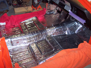
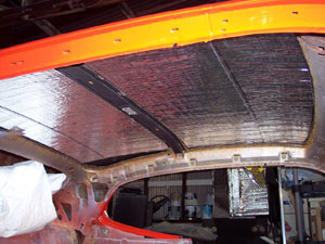
For sound and heat insulation I chose RAAMmat BXT sound deadener from RAAMaudio. It was very easy to work with, doesnt smell (butyl based, not asphalt), and sticks like crazy. Its also priced lower than Dynamat. A single 15 x 50 roll did the floor and ceiling and I have enough left to do the insides of the doors. I purchased it directly from the company and the service and delivery time were outstanding.
The stock gas tank went in next along with the fuel filler tube.
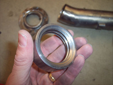
Because the Hagan fuel door has the neck going in at a different angle than stock, and because a single filler tube cant be installed once the tank is in place, I needed to do the filler in two pieces.
Hagan supplies a fitting for the end of the tube where their cap threads in. I first tried cutting the flange off the stock tube. Their fitting fit the tube just fine...
The problem is, the upper section of tubing was immediately crushed when I went to have it bent into a new shape.
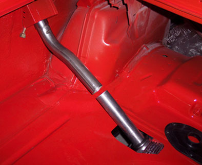
I ended up having a muffler shop bend a section of 2 stainless tubing into the shape I needed. Why stainless? No corrosion. The trouble with stainless is, its nearly impossible to do non-mandrel bends without kinking it.
So, the lower section of the stock tube was inserted into the tank with a stainless upper section.
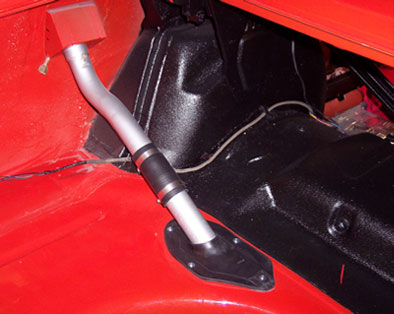
I painted the sections with Hammerite, then joined them with 2 fuel filler hose.
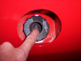
The Hagan cap allows filling without removal.
The Hagan cap allows filling without removal.
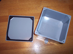
I housed the electronics for the door poppers in a plastic junction box I found in the electrical section at Lowes. It's perfect as it has mounting tabs and a gasket to keep it weather tight. Its also cheaper than some electronics project boxes.
I chose mounting it in the truck for better access, and I didn't want all that crap under the dash.
I chose mounting it in the truck for better access, and I didn't want all that crap under the dash.
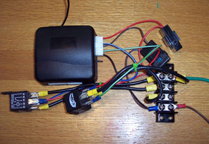
I wired the door popper electronics (receiver, relays, fuses) all together and tested thier functionality...
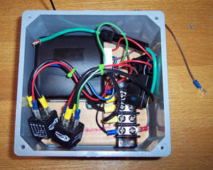
...then glued a piece of wood in the bottom of the junction box so I could mount the major components securely in place with screws inside.
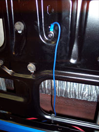
I also had to address the issue or a remote radio antenna since I had shaved the original. Most remote antennas require external power and are little more than signal amplifiers. A lot of times they work worse than the originals. So, I located a company that makes remote antennas that require no power and are specially tuned for AM/FM reception. It just needed an ex tension cable to reach the stereo up front.
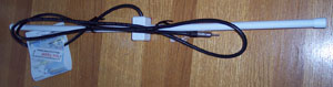
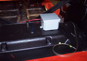
After painting the antenna black, I mounted it and the door popper electronics box in the trunk. In the picture you can also see the receiver antenna sticking up out of the box. The loose wires are for speakers.
Power for the electronics and the solenoids are fed directly from the fuse block under the dash via 6 ga. wire and then relayed back up to the doors to the solenoids.
Power for the electronics and the solenoids are fed directly from the fuse block under the dash via 6 ga. wire and then relayed back up to the doors to the solenoids.
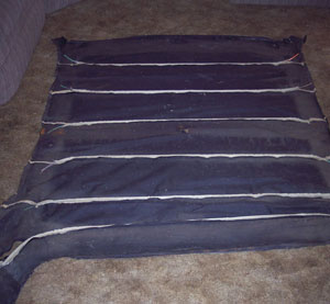
Next up came the headliner installation. I used a combination of instructions found on Resto Ricks site and a book I had.
When I removed the old liner during disassembly I simply kept the bows in their listings to keep from mixing them up. They are color coded with paint on the ends but I had no way to decode their meaning. Each one varies in length, so mixing them up will create headaches.
I laid the old liner out on the living room floor and transferred the bows to the new headliner. The listing pockets need to be trimmed back slightly when installing the bows. Just trim a little at a time.
I laid the old liner out on the living room floor and transferred the bows to the new headliner. The listing pockets need to be trimmed back slightly when installing the bows. Just trim a little at a time.
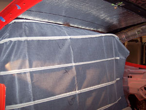
Mark the centerline of headliner and the front/rear window openings so that you can check to make sure the headliner is centered from side to side during installation.
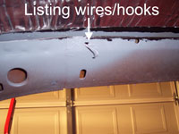
There should be little bow pockets in place along the inside of the room rails. Two listing wires or hooks are required in the rear window header panel
You simply put the ends of the rear most bow in the pockets and rotate it up into place, making sure the two hooks catch the bow. From here on, tension keeps the other bows upright. Just work your way forward one bow at a time. It goes pretty quick.
Trim the listing pockets on each end of the bows a little at a time until about 1/2 to 3/4 of bow is exposed.
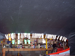
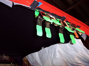
With the liner centered and the listings trimmed, I began pulling it tight at the bows and clamping with spring clamps. The material between the bows can be pulled tight too and clamped. I used clothes pins. It will take adjustments here and there but if youre patient, you can get the majority of wrinkles out.
Packing creases can be carefully warmed up with a heat gun to relax them.
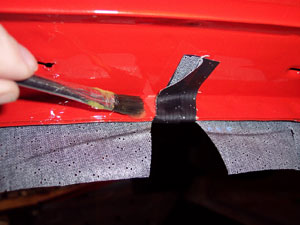
I made little relief cuts on either side of just the bow seams and then glued them to the pinch weld. Just remove one clamp at a time, apply the glue, and replace the clamp.
Once all the seams were glued and thoroughly dried, I made relief cuts as needed between the seams, section by section, gluing and reclamping as I went.
Once all the seams were glued and thoroughly dried, I made relief cuts as needed between the seams, section by section, gluing and reclamping as I went.
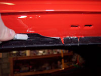
Once all the glue was cured I went back with an x-acto knife and cut off the excess.
The front and rear of the headliner are pulled and hooked onto the gripper teeth without glue.
The liner is glued to the area of the a-pillar. A cardboard panel snaps into the sail panel area and the lower edge of the headliner is glued to it (I used spray adhesive here) near the package tray.
The front and rear of the headliner are pulled and hooked onto the gripper teeth without glue.
The liner is glued to the area of the a-pillar. A cardboard panel snaps into the sail panel area and the lower edge of the headliner is glued to it (I used spray adhesive here) near the package tray.
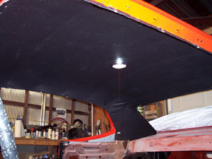
Careful use of a heat gun will remove small wrinkles.
I also re-installed the factory headliner clips I had along the roof rail pinch weld - just for extra insurance.
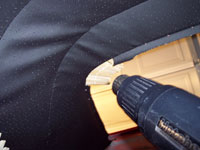
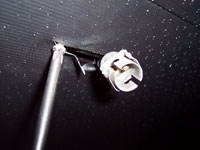
Feeling through the headliner for the dome light screws I pre-installed, I made small relief cuts just large enough to get the dome lamp socket and wiring through and access to the mounting scews. The housing and lens can then be re-installed.
I also re-installed the factory headliner clips I had along the roof rail pinch weld - just for extra insurance.
Feeling through the headliner for the dome light screws I pre-installed, I made small relief cuts just large enough to get the dome lamp socket and wiring through and access to the mounting scews. The housing and lens can then be re-installed.
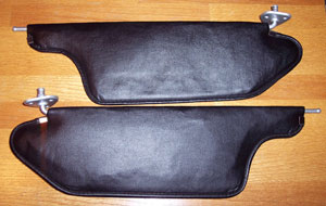
Sun visor hardware was repainted and the vinyl cleaned and sprayed with SEM vinyl and plastic dye (paint). They looked brand new when finished.
I had put the mounting screws in their holes before the headliner went in so I could easily locate them later. Just make a little slit where the head is and remove the screw.
I had put the mounting screws in their holes before the headliner went in so I could easily locate them later. Just make a little slit where the head is and remove the screw.
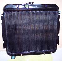
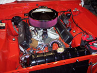
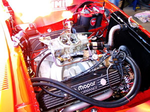
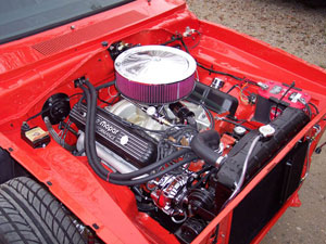
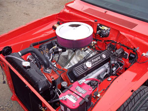
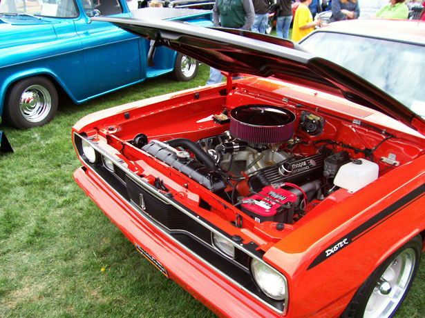
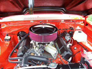
I switched my attention back to the engine compartment and one of the next things to do was locate and install a cooling fan. The reproduction (67-69) 22 big block radiator I got from U.S. Radiator had been sitting in the parts pile for years. If I hadnt already spent the money I probably would have gotten an aluminum unit and quite possibly an electric fan. I wanted to see if I could make the stock style work and I didnt want to cut core support to make room for a larger radiator - which is typical.
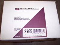
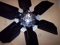
I settled on a Hayden #2765 thermal fan clutch (and fan blades #3618) purchased through a local auto parts store. The unit is intended for a Jaguar but is the shortest fan clutch available that will fit Mopars.
UPDATE: I later added a shroud, tried just an electric fan, but wasn't satisfied with the cooling until I switched to a solid fan in conjunction with the shroud and Milodon 180* thermostat.
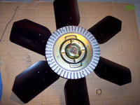
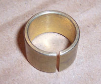
The fan clutch came with a reducer bushing so that it would fit the smaller water pump snout. Because of such shallow space, getting it bolted to the water pump is slow going with a fair amount of finger gymnastics. Once installed I had about 1/2 of clearance between the fan and radiator - just enough to slide the radiator in and out.
Lower radiator hose clearance would prove to be a problem later that was mostly solved by melting the solder on the lower hose connection and pointing the fitting in a slightly different direction.
Lower radiator hose clearance would prove to be a problem later that was mostly solved by melting the solder on the lower hose connection and pointing the fitting in a slightly different direction.
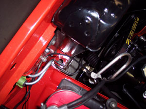
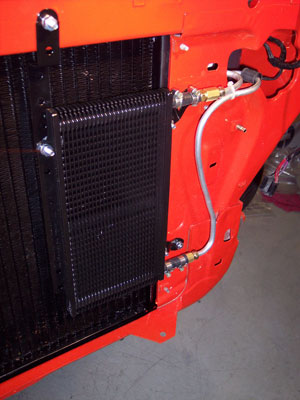
Using aluminum tubing and flair fittings, I fabbed some new sections of tranny cooler line to route fluid to a B&M Super Cooler attached to the core support.
Fluid flows through the radiator cooler first.
I used larger 3/8 tubing to fab a hard line between the mechanical fuel pump and carb too.
Fluid flows through the radiator cooler first.
I used larger 3/8 tubing to fab a hard line between the mechanical fuel pump and carb too.
By this point in time we were dangerously close to being ready to fire this thing up for the first time and break it in.
Carpet was laid and trimmed. No pics of that as its fairly straightforward. I purchased 80/20 loop from Legendary. The carpet arrived in a Trim Parts box. Its two pieces, fully molded, with jute padding glued to the back. Just a matter of trimming the excess a little at a time until trim and mouldings can go back on. No glue required.
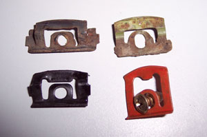
I also wanted to get the front and rear glass in before firing the engine, so window trim clips had to go in first.
I also wanted to get the front and rear glass in before firing the engine, so window trim clips had to go in first.
In my case, the front and rear trim clips were all the same except for 5 different clips at the front. I had no idea where the oddball clips went or why there were different ones (unless the factory did this when they didnt get the holes quite in the right place) After studying the trim pieces and old clips I guessed at their location based on marks and globs of sealer. I cant say with 100% certainty that I got the odd clips in the right locations but in the end the trim went back on okay.
There are 9 clips along the bottom of the windshield. I put the taller clips with the slotted holes (upper right in picture) in the following positions - counting from either end: 1,4, 5, 6, 9.
The clip kit I purchased came with 5 tall, red clips (lower right in picture). There is no way these will work. I had to call the supplier and have him send me 5 replacements like the ones above it.
While installing some of the clips I found holes that were slightly oversized and wouldnt hold the screw. A single zap with a mig welder on the edge of the offending holes did the trick - not something I was comfortable doing though around nice, new paint.
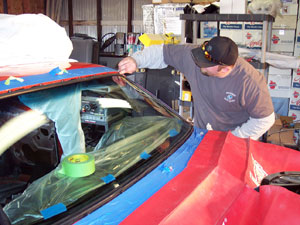
As soon as the clips were all in I had a local mobile auto glass installer come out and install a new front windshield and my original back glass.
Paying him to do the job was worth every penny.
Paying him to do the job was worth every penny.
The front and rear gaskets came from Restoration Specialties. They supplied the bulk of the gaskets and weatherstrips.
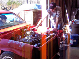
I finally gave birth on March 8, 2008.
With my son Austin watching the gauges and my wife and daughter watching for leaks and other signs of trouble, we lit it off.
Aside from a couple minor leaks the break-in commenced without a hitch. However, 10 minutes in the temps started hitting 210+. I got nervous and shut it down. After a cool-down period we resumed the break-in without incident.
With a rash of flat-tappet cam failures reported over the past few years I was particularly nervous about the break-in. Reduced zinc levels in modern oils are to blame. For break-in we used Shell Rotella T oil (diesel) along with a bottle of GM EOS additive. There was also some Power Punch in the crankcase that I put in a long time ago. Of course, we primed the oil system before firing it. These measures seemed to pay off.
To make communication easier during break-in I temporarily bolted short lengths of flex pipe and the Pypes mufflers to the ends of the Schumacher headers. It made hearing potential problems easier too.
However, our good fortune soon went south. Within a week of break-in I noticed the trans fluid was beginning to turn pink - aka: The strawberry milkshake. Water in the trans fluid. Great.
The first omen of transmission woes had actually presented itself the day before we fired the engine. A puddle of blood appeared below the bell housing. I was concerned but hoped that it was simply a case of overfilling the trans. A new puddle appeared each day following break-in until I noticed the color beginning to change.
On March 14 I pulled the tranny back out, removed the pan, and was shocked to find it filled with an enormous amount of dirt, silt, and sand. Bizarre. Radiator leaking? Maybe, but what about all the sand? The new torque converter I bought off of ebay a year earlier was suddenly looking very suspicious!
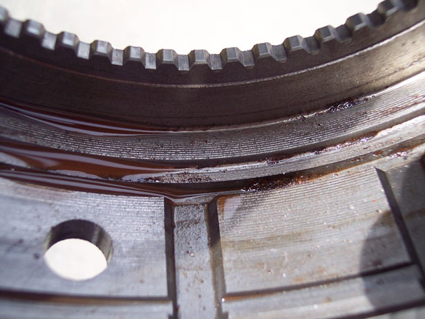
(Above) One of the drums filled with sand.
Water and clutch facings dont mix - the facing material (basically paper) tends to delaminate. Once contaminated with water you run the risk of the water turning to steam and quite literally blowing the facings off the clutches. So, I got on the phone and ordered another overhaul kit, a Transgo TF-2 shift kit (as an upgrade), and a custom built torque converter from PTC.
A couple weeks later I had it all back together and running well again: no leaks, no milkshakes, no problems.
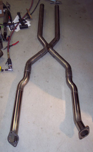
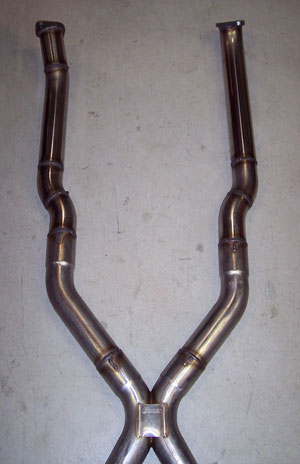
Time to get the rest of the exhaust system on... a x-pipe system from Pypes Performance.

I purchased the Pypes Performance exhaust system with their Race-Pro mufflers through Summit. Its an all stainless system that includes the tail pipes and the hardware. Course, its designed for full-length headers so I had to fabricate downpipes to join the system to the Schumacher headers. I ordered two 45 degree and two 180 degree 2.5 stainless bends made by Magnaflow. They were the least expensive stainless bends available from Summit.
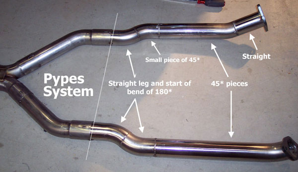
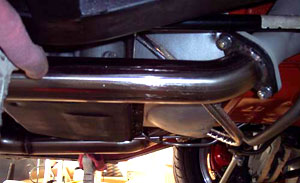
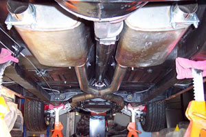
I spent a lot of time determining angles and cutting pieces to ensure the downpipes and the entire system stayed tucked up under the chassis. The downpipes basically come straight back from the collectors and then jog to pass through the cutouts in the trans crossmember. The forward sections of the x-pipe had to be shortened (off the ends where the x is) in order to bring them closer together and meet the downpipes.
Bear in mind that the headers dump and are angled differently on each side of the engine. The cross member cutouts are also offset (remember the trans tunnel offset?) so nothing is symmetrical. Dont cut two identical pieces of pipe and expect them to fit both sides.
I tacked the pieces together with a mig welder and then took everything down to a muffler shop to have the joints fully welded with stainless wire.
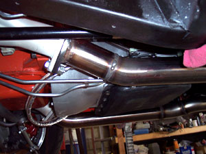
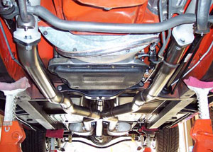
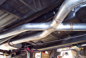
For now, I decided to not install the tail pipes. I kinda like the noise. I took some leftover pipe and cut a couple turn-down sections (not pictured) to direct the exhaust to the ground.
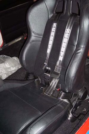
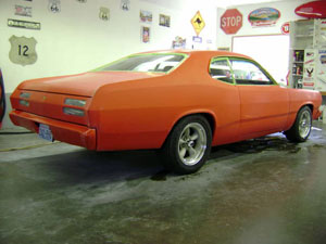
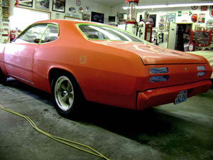
While the wife and kids leave for Spring break (1st week in April) I take that time to kick things into high gear. Ive set deadline for myself of May 2 for completion and entry into our first show (Washington Apple Blossom Festival - Classy Chassis Parade & Car Show). Thats when the exhaust was fabbed, tail lights, rear quarter pop-out windows (after rebuilding them earlier), package tray, interior panels, etc. were all installed. It was also time to install safety belts and bolt a seat in for a road test...!
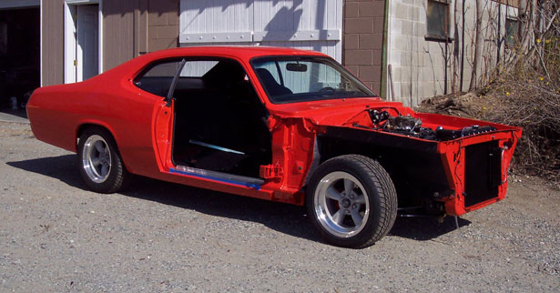
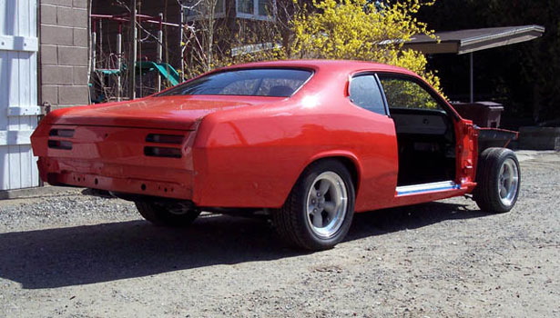
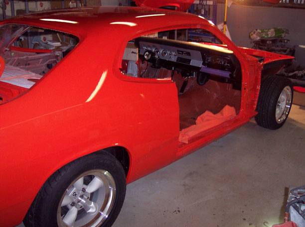
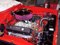
...Yup, above is just the way it looked when I rolled it out for the first road test around the quiet little neighborhood. Lets just say it performed admirably right out of the box. Later I adjusted the timing and ultimately changed the pump shot cam and squirter on the Holley 850DP.
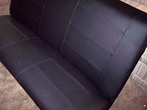
One of the big projects left to do was to recover the rear seat to better match the pattern of front aftermarket buckets. I found some faux leather at the local Joann Fabric store. Its made by Spradling and is from their Whisper line - same stuff used by trim shops.
I used the old cover for measurements and as a pattern for certain pieces. I stitched it up using my wifes Pfaff home machine with French seams and no piping - like the fronts. Many years ago I worked in a clothing factory as a machine mechanic so that experience came in handy here.
I used the old cover for measurements and as a pattern for certain pieces. I stitched it up using my wifes Pfaff home machine with French seams and no piping - like the fronts. Many years ago I worked in a clothing factory as a machine mechanic so that experience came in handy here.
During the latter part of April we hung the doors, fenders, and test fit the hood again. Didnt take any pictures of any of this. My daughter Whitney (15 at the time) helped me adjust gaps and install the window assemblies.
Reinstalling all the window hardware can seem to be a daunting puzzle. But with the help of a factory service manual it actually went pretty quick. Knowing the sequence in which the pieces must go in is key. She also helped me install the weatherstrips, door latches and solenoids. An extra set of hands at this stage is very helpful.
Reinstalling all the window hardware can seem to be a daunting puzzle. But with the help of a factory service manual it actually went pretty quick. Knowing the sequence in which the pieces must go in is key. She also helped me install the weatherstrips, door latches and solenoids. An extra set of hands at this stage is very helpful.
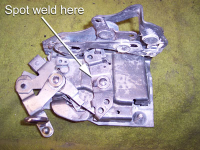
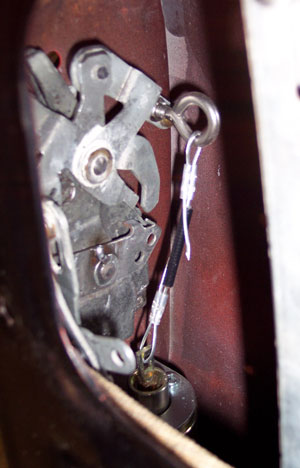
The door latches were first modified for use with solenoids by spot welding the lock mechanism so that it cant accidently be moved into the locked position by some freak of nature. If this were to happen, youd be screwed. With the solenoids, door locks of any kind are no longer necessary.
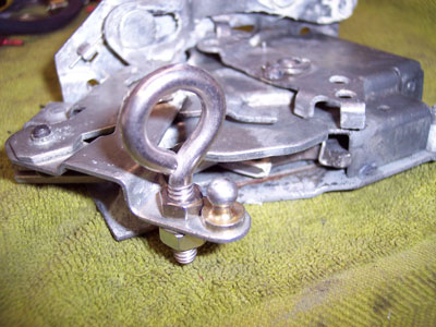
I added a high-strength stainless eye-bolt at the point where a rod normally attaches to release the mechanism.
Once installed, a straight pull down from the solenoid mounted below releases the latch.
Once installed, a straight pull down from the solenoid mounted below releases the latch.
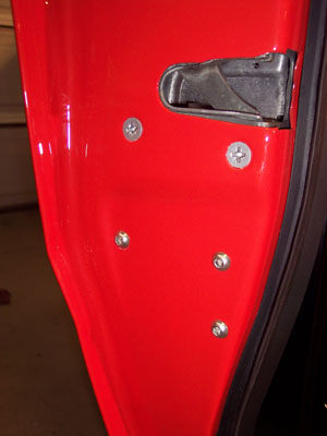
(Above) Stainless cap screws indicate the mounting location of the solenoid below the latch.
Inside the door you can see the cable between the solenoid and latch. A little slack in the cable is necessary for proper operation. Without enough slack, it cant fire. But when it does, theres 50lbs. of pull.
I ran a separate ground wire from the solenoid mounting bracket to another part of the door structure to ensure a good ground.
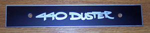
For an added touch on the interior of the doors I decided to replace the odd plastic emblems on the upper door frame (used to hide window related hardware access holes) with polished aluminum plates and custom logos.
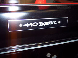
A good friend of mine does vinyl graphics so I had him do the logos and apply them. The black field and silver letters (which dont show well in the picture) are vinyl. The outline of the numbers and letters is the aluminum showing through
I drilled new holes in the doors and attached them with torx head screws with sheetmetal threads. Theyre not easy to find.
I drilled new holes in the doors and attached them with torx head screws with sheetmetal threads. Theyre not easy to find.
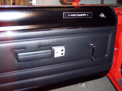
The doors were finished off (later) with panels from Legendary. I chose the 71 pattern because its cleaner with simple lines.
The arm rest bases were in tough shape so I sprayed them with a texture black paint. The arm rests were new...
And yes, the door handle treatment is a direct rip-off from the Dust-Ya project car.
The arm rest bases were in tough shape so I sprayed them with a texture black paint. The arm rests were new...
And yes, the door handle treatment is a direct rip-off from the Dust-Ya project car.
On April 27th, just 5 days before the show, I took the car to a woman in the area famous for her cutting and buffing skills. Im glad I wasnt there to see the carnage. She color sanded the finish and buffed it back to a mirror shine. The paint looked good before but when she got done with it, it looked fantastic. The minor peel and trash that are inevitable in all paint jobs were gone.
We werent able to get the car back from her till Friday around noon. The car had to be done in the next few hours.
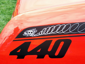
Another good friend of mine, experienced in vinyl graphics, came on short notice and applied the stripe set from Performance Car Graphics. I went with 72 side stripes with the engine displacement call-outs and a 71 tail panel stripe. No pics of this installation either but the tail panel stripe was a pain, even for my experienced friend.
At 3pm my wife helped me install the side mirrors, door panels, hood, and headlight bezels. Phew!
We werent able to get the car back from her till Friday around noon. The car had to be done in the next few hours.
Another good friend of mine, experienced in vinyl graphics, came on short notice and applied the stripe set from Performance Car Graphics. I went with 72 side stripes with the engine displacement call-outs and a 71 tail panel stripe. No pics of this installation either but the tail panel stripe was a pain, even for my experienced friend.
At 3pm my wife helped me install the side mirrors, door panels, hood, and headlight bezels. Phew!

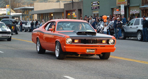
At 5pm, my son and I rolled out for the start of a two day show that began that evening with a parade. The following day we participated in the formal show. There was a huge field of cars of all makes, models, and years. We managed to take first in our class (1970s Modified) - a strangely satisfying reward after nearly 6 years of work.
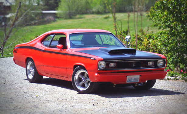
And thats about it. Yeah, there are some little odds and ends yet to take care of but isnt that always the case? Im sure therell be little changes, additions, and mods as time goes on. Thats the nature of these projects and the fuel behind the hobby. Hope youve enjoyed my journey.

Yeah, yeah, I know. I should have known better...
I found a TCI torque converter on ebay that was advertised as having been bought new and never installed. Under the circumstances it seemed like a decent deal. The seller even lived in my state just a couple hours away. I scored it and when it arrived it indeed appeared to be new - in its original box and everything. The box did look a little worse for wear though with some obvious water damage. There was some light surface rust on the snout... (Hmmmmmm)
I joined the trans to the engine on the dolly almost a year before break-in. While attempting to pre-fill the converter I noticed it wouldnt hardly take any fluid - it just sat there in the snout... (Hmmmmmm)
After the great strawberry milkshake debacle, and finding sand inside the tranny, and having a radiator shop confirm that there were no holes in my new radiator, I emailed the guy who sold it to me (a regular on one of the Mopar boards, incidently) and inquired (without making any accusations) if he knew whether the converter had ever been involved in a flood. (After all, he lived in an area known for flooding). He denied it and claimed the water damage to the box had come from a coolant leak in his garage. (That must have been some coolant leak!) He said he had purchased it from Summit Racing and after deciding it wasnt what he wanted, too much time had passed to return it.
Fact or fiction? Who knows for sure. But I do know it caused me an awful lot of headache, lost time, and wasted money. Live and learn.
Tale of an ebay torque converter
 |
 |
 |
 |
 |
 |
 |
 |
 |
© 2013 JP Herrick Enterprises - All Rights Reserved
Site updated: January 2014
